Author Archives: Sean - Page 3

APRS

Finally, I’ve gotten my APRS stations coordinated. I have a weather station transmitting via TCP/IP APRS, my iPhone portable station transmitting via TCP/IP APRS, and my mobile station transmitting via RF (using a TinyTrak4 by Byonics).

APRS works by sending a digital packet of information, via RF, to a receiving station (anyone can have a receiving station at their house with a receiver, computer, and Internet service), and then that station (referred to as an iGate) sends the information to the APRS servers via the Internet. The default 2-meter frequency used is 144.3900MHz, and so as you’re out driving (for example), you set your transceiver to 144.390, turn on your APRS TNC (in my case, a TinyTrak4), and it does the rest.

There are also “digipeaters” that listen for your packets and repeat them again, so they may be passed to an iGate, to be uploaded to the Internet APRS servers. I have my TinyTrak4 set up as a digipeater to repeat any path requests with “TEMP” or “SAR” in them. That means if my station hears another station with “TEMP” or “SAR” programmed in, it will repeat it for them. I do this because “TEMP” is used for temporary situations, such as Field Day or perhaps emergency or other situations, and “SAR” is used for search and rescue operations. If I participate in such events, I’m already set up to be of assistance by helping to get their packets out to an iGate, which can upload them to the Internet APRS servers.

There’s lots of reading out there on APRS; just go to Google and type in APRS Amateur Radio!


3-element Tape Measure Yagi

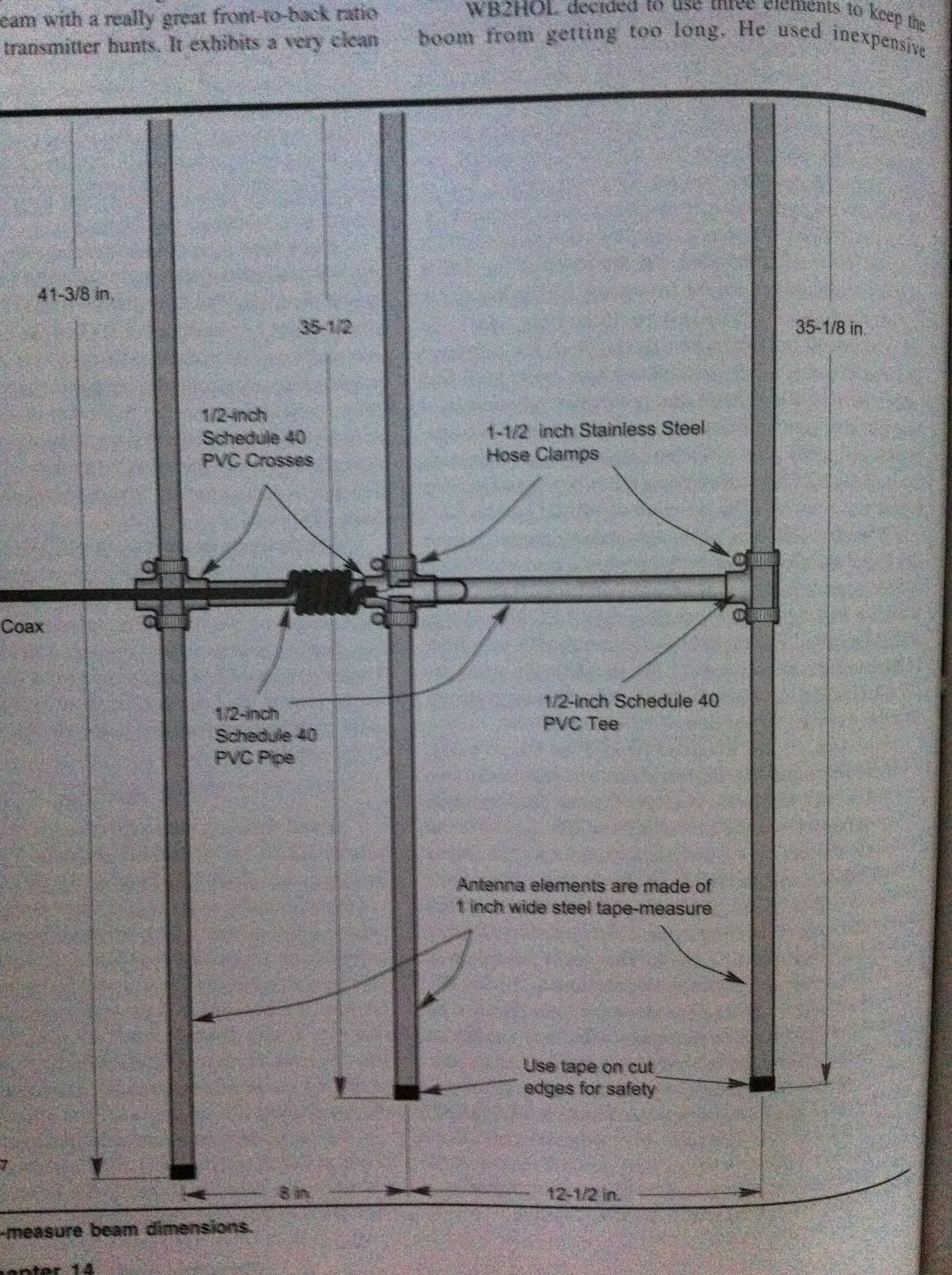
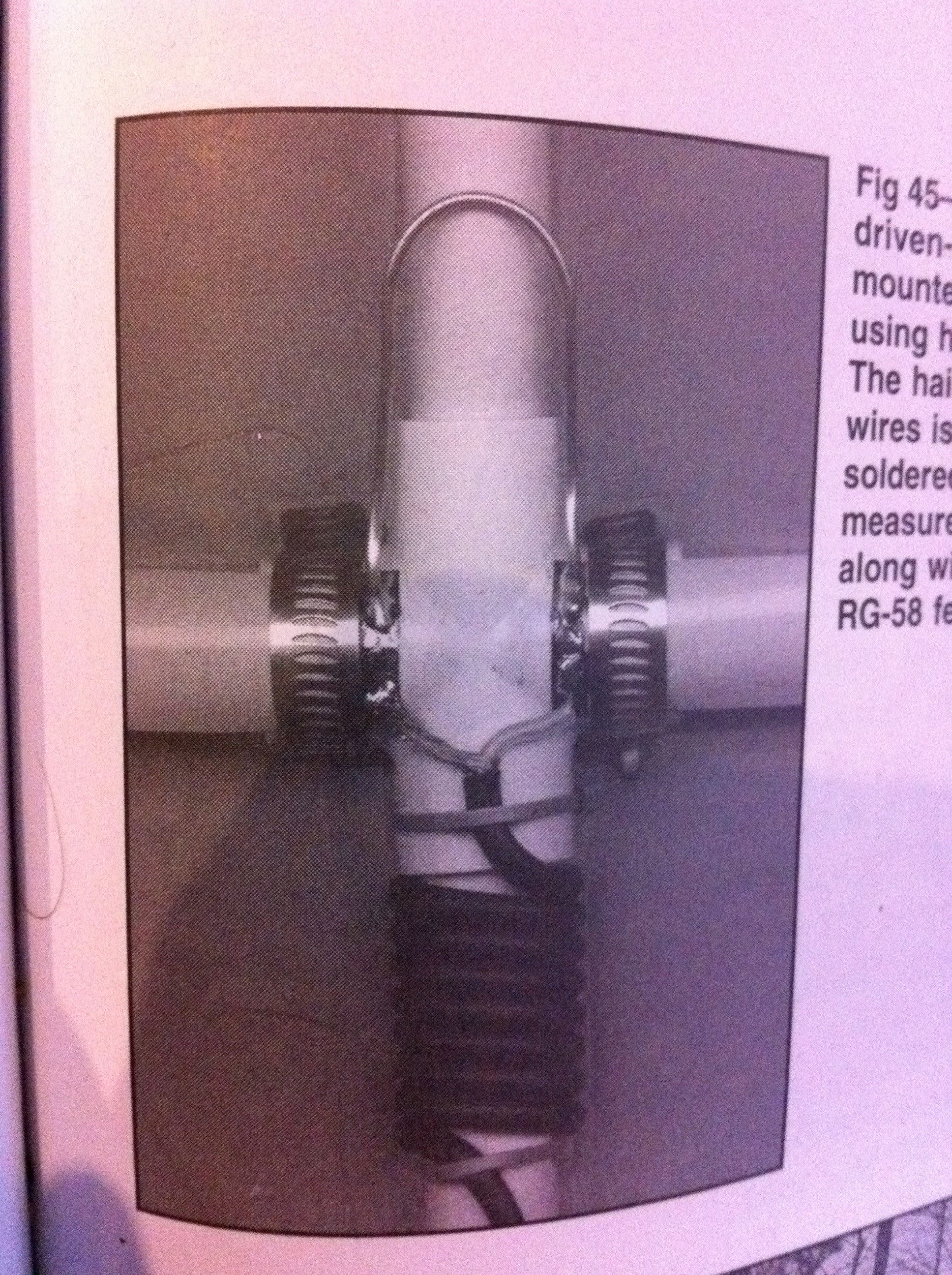
I’ve been wanting to build an antenna for radio direction finding (RDF) for a long time. I finally got the motivation to build one, so here are a couple pictures of the design from the ARRL Antenna Book. For pictures and more explanation from my build, check out the Projects Page.

Here is the design schematic.

Here is the matching section where the coax connects to the driven element.

It was a lot of fun to build and very easy to do. I recommend it for anyone interested in RDF or who needs a portable yagi for anything (including satellite work)!

To view more about the project, check out the specific Project page, called Tape Measure Yagi.

January ARRL VHF Sweepstakes

Don’t forget about the VHF Sweeps coming up this weekend!

VHF Sweepstakes

From the ARRL’s Contest Website:

To work as many amateur stations in as many different 2 degrees x 1 degree grid squares as possible using authorized frequencies above 50 MHz. Foreign stations work W/VE amateurs only.

Begins 1900 UTC Saturday, ends 0359 UTC Monday (January 22-24, 2011). On all authorized frequencies above 50 MHz (6 Meters).

Single Operator, High Power:

1500 Watts PEP or the maximum allowable power level established by the national licensing authority of your country, whichever is lower.

Single Operator, Low Power:

50 MHz and 144 MHz–200 W PEP.

222 MHz and 432 MHz–100 W PEP.

902 MHz and above–10 W PEP.

Single Operator Portable:

Ten (10) W PEP output or less.

Portable power source.

Portable equipment and antennas.

Multioperator:

1500 Watts PEP or the maximum allowable power level established by the national licensing authority of your country, whichever is lower.

Limited Multioperator:

1500 Watts PEP or the maximum allowable power level established by the national licensing authority of your country, whichever is lower.

Rover:

1500 Watts PEP or the maximum allowable power level established by the national licensing authority of your country, whichever is lower.

Limited Rover:

50 MHz and 144 MHz–200 W PEP.

222 MHz and 432 MHz–100 W PEP.

902 MHz and above–10 W PEP.

Unlimited Rover:

1500 Watts PEP or the maximum allowable power level established by the national licensing authority of your country, whichever is lower.

Certificates will be awarded in the following categories:

Single Operator: – Top Single Operator in each ARRL/RAC Section for high and low power.

– Top Single Operator on each band (50, 144, 222, 432, 902, 1296 and 2304-and-up categories) in each ARRL/RAC Section where significant effort or competition is evident. (Note: Since the highest score per band will be the award winner for that band, an entrant may win a certificate with additional single-band endorsements.) For example, if KA1RWY has the highest single-operator all-band score in the CT Section and her 50- and 222-MHz scores are higher than any other CT single operator

4-element Tin Foil Quad

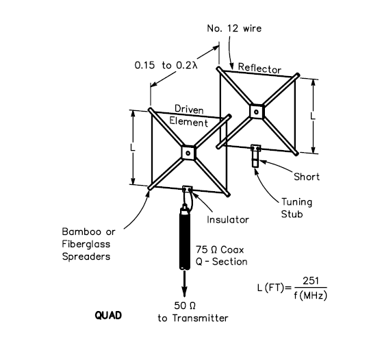
With the ARRL VHF Sweepstakes coming up this weekend, I wanted to construct a directional beam antenna for use on one of the local mountains for some of the contest. I wanted something that is simple, cheap, quick, portable, and, most importantly, effective. I thought back and recalled a single element quad antenna for 2-meters that I had constructed in college, for my amateur radio club to use locally. I wanted to make it more effective, so I decided to try to work out a design for a multiple element quad for 2-meters.

Here’s what a quad antenna looks like. This is a 2-element design.

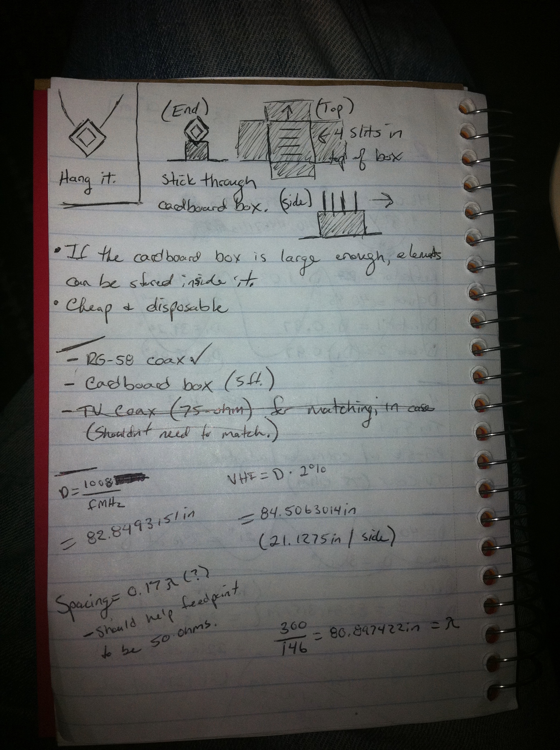
My “design” will have four elements, a reflector, driven, and two directors. This will help to focus the beam of RF energy into a more concentrated and condensed area. That basically helps to add gain and sensitivity in the direction that the beam is pointing. The elements will be taped to square (diamond) shaped pieces of cardboard, and will be made of one strip of tin foil, 1/2″ wide, in a way that will trace the edge of the cardboard. The completed cardboard elements will then be placed in to slits made in the bottom of a large cardboard box, which will sit on its top as a support for the antenna. Tuning (if necessary) will be achieved by placing the driven element in different pre-tested and tuned slits.

Here’s what my design looks like so far. Crude, isn’t it?

Last night, I bought some of the supplies that I will need. 50ft. of RG-58 coax. I asked at the local Lowe’s if they had a cardboard box that I could have, because I will need to have one about 5ft. in length to accommodate the elements of the antenna. I already have tin foil and solder / soldering iron at home. That’s about all I will need. I will post this project, along with pictures, once it is completed, on the “Projects” page.

January ARRL Contests

Happy New Year. Hope this one is fun! Let’s talk about the ARRL Contests that are yet to come this month. You can always get a look at the contest calendar by following this link: http://www.arrl.org/contest-calendar.

January 8-9 – RTTY Roundup

From the ARRL’s Contest Website:

Amateurs worldwide contact and exchange QSO information with other amateurs using digital modes (Baudot RTTY, ASCII, AMTOR, PSK31, and Packet …

EDIT: This post has been lost due to operator error! Sorry!

Dipolish Thoughts

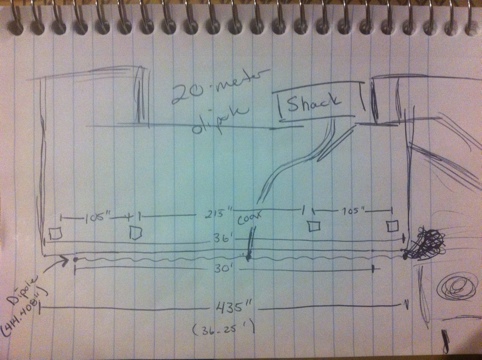
Lately, I’ve been wishing that I had a better way to get out on 20-meters, 40-meters, and 75-meters. The 75- and 40-meters are a bit long for the small amount of space that I have available to hide an antenna (local residential, contractual restrictions), but I did some measuring around, and I think I found an ok spot to try to string a dipole!

Check out these drawings I made late at night (mind I’m no artist).


Probably hard to conceptualize my diagram in your mind, but I have a deck over a patio outside of the “Shack.” There are 4 beams that support the deck that I believe I can string the dipole from! I will try to get the supplies and cut this to length very carefully–I don’t have an antenna tuner. I’m hoping I can also tune on 10-meters, as a full wave dipole. I will probably post pictures and such on the Projects page as I go.

Strange Digital

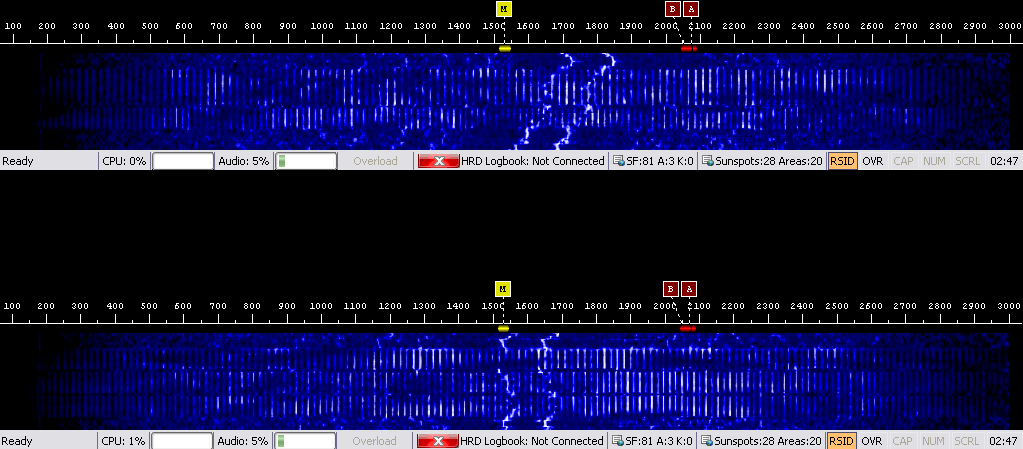
I was tuning around this morning at about 0730 Zulu, and I flipped my radio to 5 MHz. I stopped on 5.332, where I heard a strange digital sound, rapidly pulsing. I opened up Digital Master 780, and took a couple of screenshots of what I heard. If you can identify this mode, I would be very interested in finding out what it is, so I can receive and possibly transmit it!

The two squiggley lines are non-related. The vertical lines are the signal as depicted by Digital Master 780’s waterfall display. Click the image to view larger.

Sea Water Antenna

I posted this on my Twitter when it came out, but I wanted to re-post it here, to share again. This is a sea water antenna that was designed and can be used in a variety of applications. I thought it was a very neat concept, and I would even like to try building one. It isn’t high on my priority list right now, but it would definitely make for a fun and interesting experiment.

SPAWAR Systems Center Pacific has developed a technology that uses the magnetic induction properties of sodium chloride (salt) in sea water to create a UHF/VHF/HF antenna.

(From http://www.southgatearc.org/news/october2010/sea_water_antenna.htm)

More Fractals

I wanted to share a video with you that was shared with me by a friend (thanks David). It’s discussing fractals, fractal geometry, and how they came to be. It’s about 1 hour long, and was an episode on Nova, on PBS. I would love to discuss these more with someone, so please feel free to contact me or comment on my page to start a discussion!

Nova: Hunting the Hidden Dimension

Fractal Antennas

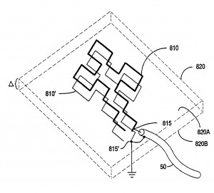
I’ve been doing some reading on fractal antennas lately, after having disregarded it the first time I came across it some time ago (thanks, David). It’s seeming to intrigue me quite a bit, and so I am contemplating a project to construct some form of fractal antenna for use, perhaps, on UHF/VHF. I will continue to research online and try to find or create a suitable pattern/layout for the elements. If you have any knowledge, experience, or information otherwise about fractal antennas, please leave a comment here!

Credit: http://www.freepatentsonline.com/7019695.html

http://www.freepatentsonline.com/7019695.html