
Threw my barometer, hygrometer, and thermometer outside of the window tonight. It’s super temporary, but it’s one baby step closer to getting things running. Currently located within a couple of feet of my house, temperature, humidity, and pressure are available at the right hand side of my page, on the weather page of this site, and at WunderGround and on APRS.
Category Archives: Projects
1-wire Wx Station Testing
Posted by Sean
on July 17, 2013
Comments Off on 1-wire Wx Station Testing
Set out the 1-wire wx station to calibrate the sensors before mounting them in any semi-permanent way. My anemometer and windvane are placed between my and my neighbor’s house. It is a less than ideal position, but the length of ethernet cable is limited with this particular setup. So far, I have done one calibration on the three (of four) thermometers in my station, two contained in the Temperature/Humidity/Solar sensor and one contained in the Barometer. I recently repositioned those three thermometers to my back yard, from my driveway (which gave far too high temperature readings). I also created a makeshift radiation shield made from styrofoam and zipties.
I also updated the Website in a few places to show my weather data and webcam. You can see my weather data on the right side of the Home page of my Website and on the Weather page. The data is also transmitting to APRS-IS (Automatic Packet Reporting System) via Internet (this is considered “APRSWXNET“), which is then fed to the CWOP (Citizens Weather Observation Program), which is used by the NWS (National Weather Service) via the MADIS Program for forecasting and other purposes.
Slight Updates
Posted by Sean
on July 2, 2013
Comments Off on Slight Updates
Made a few modest updates relating to my personal (1-wire) weather station (mainly the Website). Plan to tower-mount it as soon as possible. Data being sent to APRS-IS and WunderGround. Data visible in the right hand column and on the Weather page. Also added APRS tracking to the right hand column that shows my position as I am using APRS in my vehicle (storm chasing or otherwise).
Sean
Severe Wx
Posted by Sean
on June 12, 2011
Comments Off on Severe Wx
Lately, I’ve been getting back in to SKYWARN severe weather spotting around Coshocton County, Ohio. It’s been a good bit of fun getting my portable wx station set up, but the really fun part is using it! (To see my portable wx station, click here.)
I still need to devise a way to latch this sucker down in very high winds. I’m experimenting with bungee cords and the roof of my car, but in the last storm, I didn’t have enough bungees to properly secure it, so I had to disengage it and just go without any data. Unfortunately, in my county, AT&T does not offer any coverage whatsoever, and I have no cell data available to me, so I can’t even view a radar image. It SUCKS, but I’m working on getting my own large area WiFi signal out, so I can access the Internet that way on my iPhone or netbook laptop.
I’ll post some pictures and updates about my trials and tribulations with the wx station as they become available (meaning, if I’m not being blown around in 40MPH winds, losing my hat, and trying to keep my station from falling over)!
1-wire Wx Station Project
Posted by Sean
on March 1, 2011
Comments Off on 1-wire Wx Station Project
Added a new page to the Projects Page. It’s about my portable 1-wire Weather Station. Check that out!
APRS
Posted by Sean
on February 18, 2011
Comments Off on APRS
Finally, I’ve gotten my APRS stations coordinated. I have a weather station transmitting via TCP/IP APRS, my iPhone portable station transmitting via TCP/IP APRS, and my mobile station transmitting via RF (using a TinyTrak4 by Byonics).
APRS works by sending a digital packet of information, via RF, to a receiving station (anyone can have a receiving station at their house with a receiver, computer, and Internet service), and then that station (referred to as an iGate) sends the information to the APRS servers via the Internet. The default 2-meter frequency used is 144.3900MHz, and so as you’re out driving (for example), you set your transceiver to 144.390, turn on your APRS TNC (in my case, a TinyTrak4), and it does the rest.
There are also “digipeaters” that listen for your packets and repeat them again, so they may be passed to an iGate, to be uploaded to the Internet APRS servers. I have my TinyTrak4 set up as a digipeater to repeat any path requests with “TEMP” or “SAR” in them. That means if my station hears another station with “TEMP” or “SAR” programmed in, it will repeat it for them. I do this because “TEMP” is used for temporary situations, such as Field Day or perhaps emergency or other situations, and “SAR” is used for search and rescue operations. If I participate in such events, I’m already set up to be of assistance by helping to get their packets out to an iGate, which can upload them to the Internet APRS servers.
There’s lots of reading out there on APRS; just go to Google and type in APRS Amateur Radio!
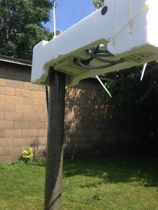
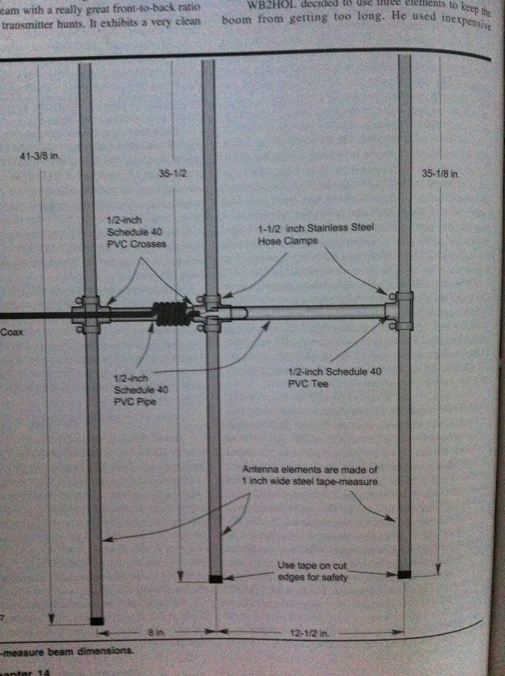
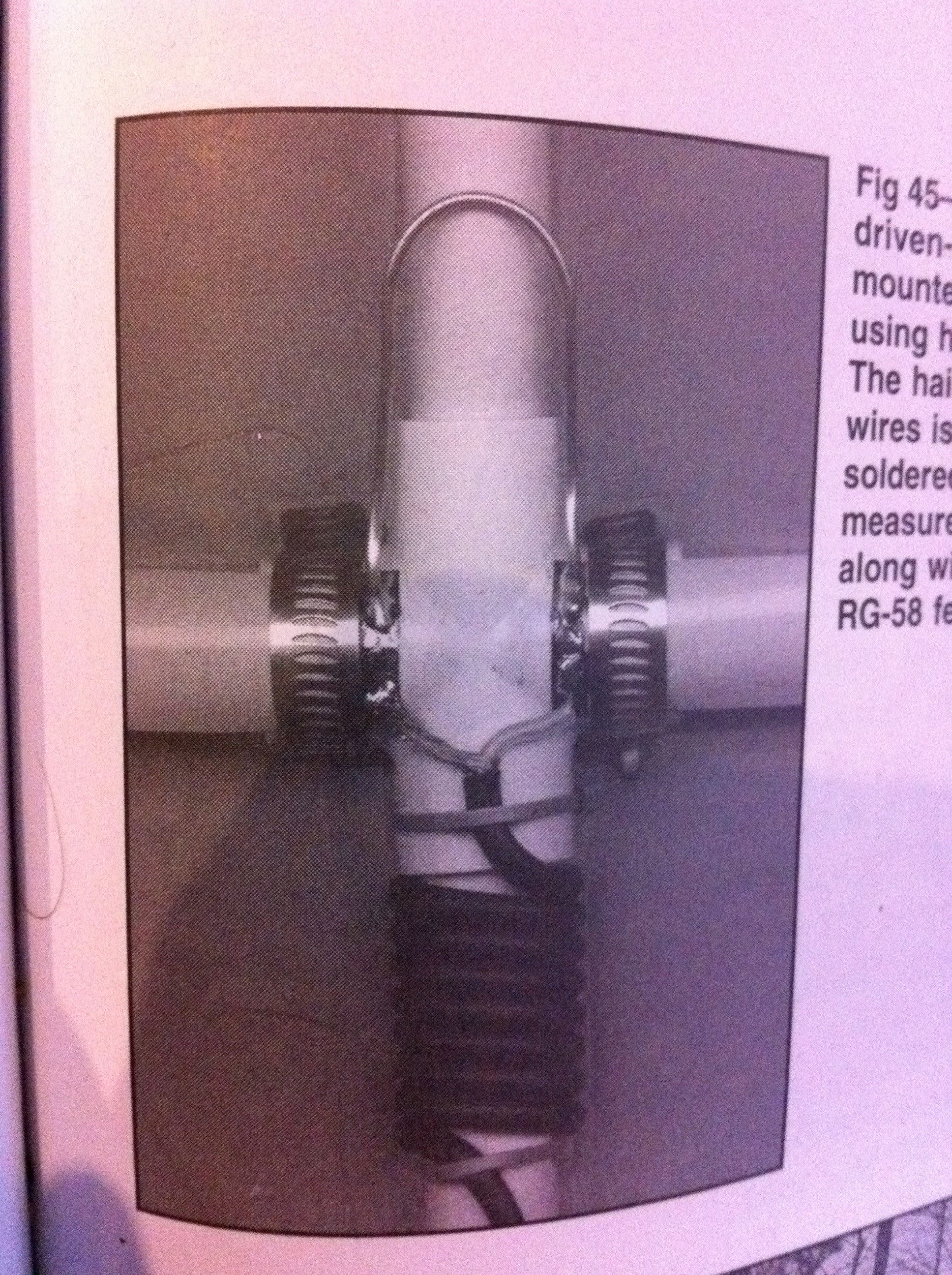
3-element Tape Measure Yagi
Posted by Sean
on February 6, 2011
Comments Off on 3-element Tape Measure Yagi
I’ve been wanting to build an antenna for radio direction finding (RDF) for a long time. I finally got the motivation to build one, so here are a couple pictures of the design from the ARRL Antenna Book. For pictures and more explanation from my build, check out the Projects Page.
Here is the design schematic.
Here is the matching section where the coax connects to the driven element.
It was a lot of fun to build and very easy to do. I recommend it for anyone interested in RDF or who needs a portable yagi for anything (including satellite work)!
To view more about the project, check out the specific Project page, called Tape Measure Yagi.
4-element Tin Foil Quad
Posted by Sean
on January 19, 2011
Comments Off on 4-element Tin Foil Quad
With the ARRL VHF Sweepstakes coming up this weekend, I wanted to construct a directional beam antenna for use on one of the local mountains for some of the contest. I wanted something that is simple, cheap, quick, portable, and, most importantly, effective. I thought back and recalled a single element quad antenna for 2-meters that I had constructed in college, for my amateur radio club to use locally. I wanted to make it more effective, so I decided to try to work out a design for a multiple element quad for 2-meters.
Here’s what a quad antenna looks like. This is a 2-element design.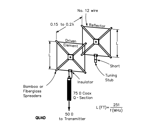
My “design” will have four elements, a reflector, driven, and two directors. This will help to focus the beam of RF energy into a more concentrated and condensed area. That basically helps to add gain and sensitivity in the direction that the beam is pointing. The elements will be taped to square (diamond) shaped pieces of cardboard, and will be made of one strip of tin foil, 1/2″ wide, in a way that will trace the edge of the cardboard. The completed cardboard elements will then be placed in to slits made in the bottom of a large cardboard box, which will sit on its top as a support for the antenna. Tuning (if necessary) will be achieved by placing the driven element in different pre-tested and tuned slits.
Here’s what my design looks like so far. Crude, isn’t it?
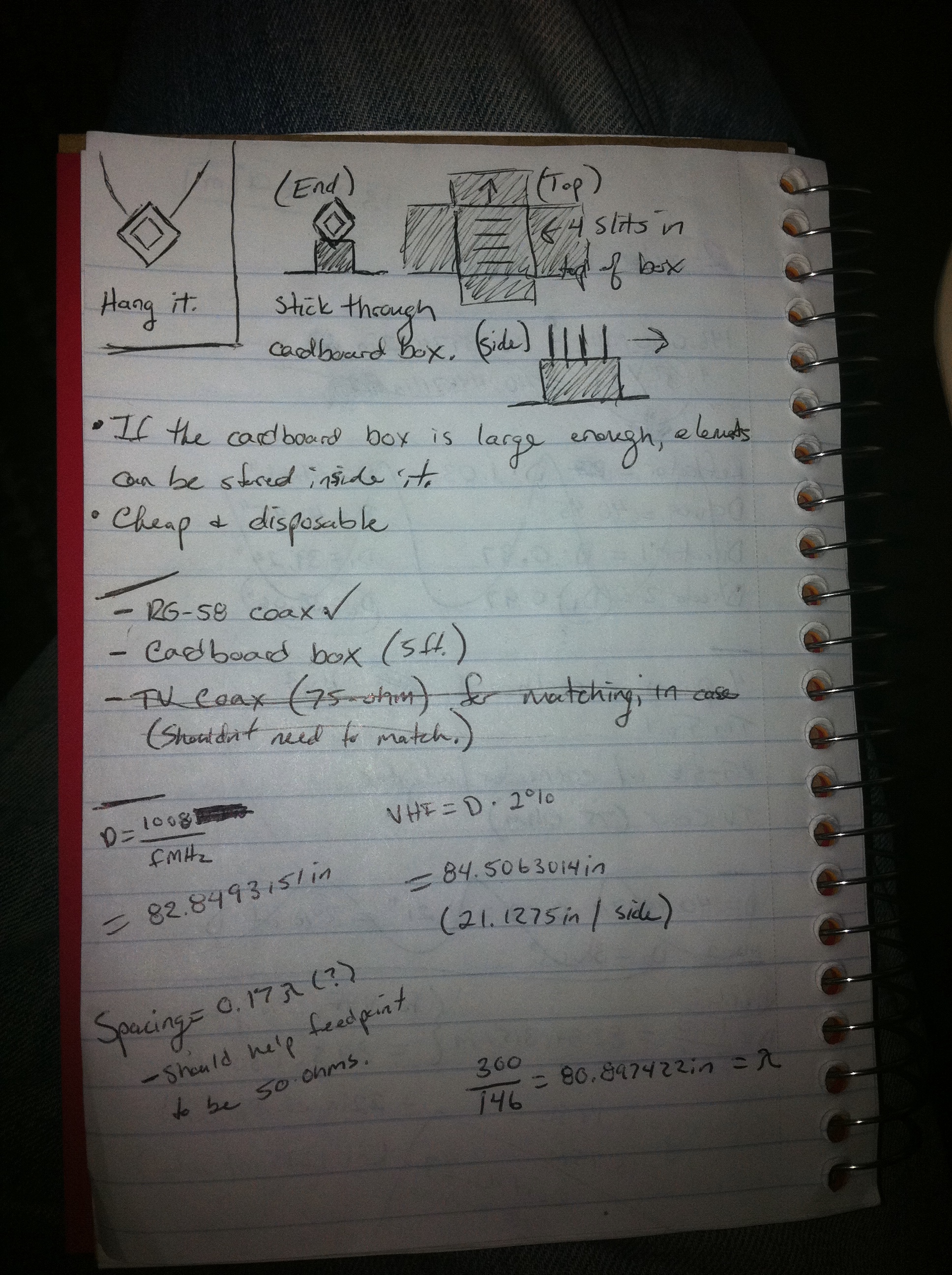
Last night, I bought some of the supplies that I will need. 50ft. of RG-58 coax. I asked at the local Lowe’s if they had a cardboard box that I could have, because I will need to have one about 5ft. in length to accommodate the elements of the antenna. I already have tin foil and solder / soldering iron at home. That’s about all I will need. I will post this project, along with pictures, once it is completed, on the “Projects” page.
Dipolish Thoughts
Posted by Sean
on January 2, 2011
Comments Off on Dipolish Thoughts
Lately, I’ve been wishing that I had a better way to get out on 20-meters, 40-meters, and 75-meters. The 75- and 40-meters are a bit long for the small amount of space that I have available to hide an antenna (local residential, contractual restrictions), but I did some measuring around, and I think I found an ok spot to try to string a dipole!
Check out these drawings I made late at night (mind I’m no artist).

Probably hard to conceptualize my diagram in your mind, but I have a deck over a patio outside of the “Shack.” There are 4 beams that support the deck that I believe I can string the dipole from! I will try to get the supplies and cut this to length very carefully–I don’t have an antenna tuner. I’m hoping I can also tune on 10-meters, as a full wave dipole. I will probably post pictures and such on the Projects page as I go.