This is a directional antenna for 2-meters. It can be used for satellite work, RDF (radio direction finding), or as a fixed antenna. It can be easily rotated by hand for circular polarization, or oriented either horizontally or vertically for those polarizations. This project is very simple to execute, and cheap, too. Here’s what you’ll need:
- (1) 20′ length of RG-58 coax
- (1) 5″ length of 12 gauge copper wire
- (1) tape measure
- (2) 1/2″ schedule 40 PVC crosses
- (1) 1/2″ schedule 40 PVC tee
- (5′) 1/2″ schedule 40 PVC pipe
- (6) 1-1/2″ stainless steel hose clamps*
- Zip ties*
- Super glue
- Soldering iron
- Solder
- Flux paste*
- Electrical tape
- Saw
- Wire strippers*
- Scissors or shears
* – optional
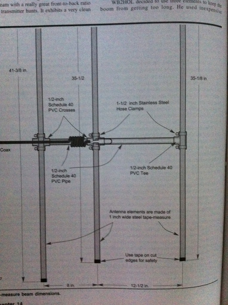
The directions are in the ARRL Antenna Book, and I followed those plans pretty closely. The method is simple. Cut the PVC pipe 11.5″ back from the end, then 7″ back from the new end. This will give you your element spacing. Connect the pieces back together (in the order that you cut) via the PVC crosses. Gluing is unnecessary. Put the PVC tee on the end. Then, cut the tape measure in to the elements with your scissors or shears. Refer to the diagram for the dimensions of each element. Remember to pay attention to the fact that the driven element will be cut in the middle and have a spacing between each side. The diagram shows a measurement for the overall length of the element, including that gap. After you cut each element, be sure to cover the ends with electrical tape. They’re quite sharp.
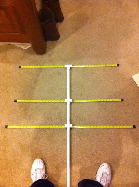
Here’s what my elements looked like when I laid them under the PVC as a “dry test fitting.”
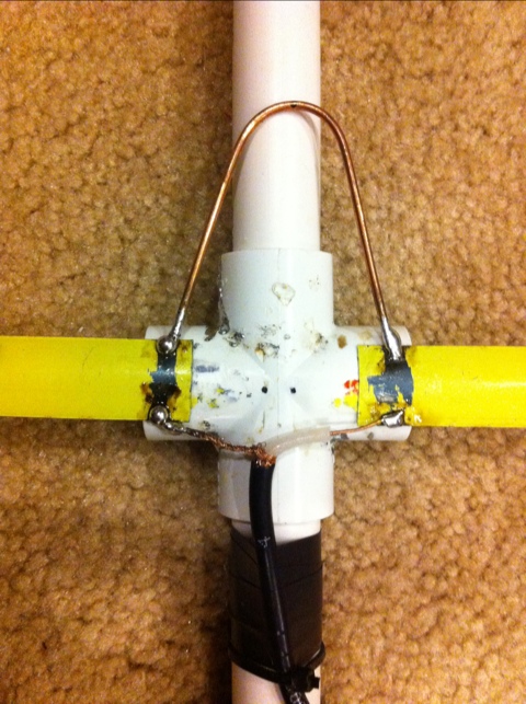
Next is soldering the coax to the matching section. The matching section is made from the 5″ length of 12 gauge copper wire, and should be bent around a 1″ cylindrical form. I marked the center of the copper wire, then used the handle of my wire strippers to bend it in to the “U” shape as in the diagram. Strip the coax so you have positive and negative leads, then solder to the tops of the “U.”
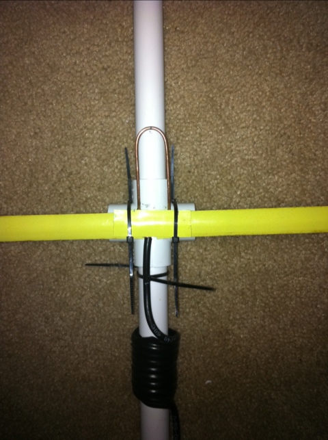
I accidentally bought 1/2″ hose clamps instead of 1-1/2″, so I opted to use super glue instead. Glue or clamp your director and reflector in place on the crosses. Find the center of your driven element and cut it in two. Now you want to use something sharp to scrape the paint off of the ends of the elements. I found it easier to do this after they were glued in place. If you’re using glue, glue them with a 1″ gap between them. Then scrape the paint off of the ends at the gap, so your coax will make a good electrical connection. I used excess measuring tape and cut about 2″ to use as a means of securing the coax and the matching section to the measuring tape. I put this over the coax and matching section like the top slice of bread in a sandwich. Zip ties were used to then hold the top slice of bread measuring tape down and, subsequently, the coax and measuring section as well. (Refer to the picture below to see how it turned out for me.) I also used zip ties to hold the coax in place temporarily. Once I have the SWR matched properly, I will attempt to solder the matching section and coax to the measuring tape directly, with flux paste.
If you’re using clamps, clamp the elements down and then solder the matching section to the top side and the coax to the bottom side of the measuring tape. You’ll need to use some flux paste if you do it this way; I found the solder wouldn’t stick too easily to the measuring tape. The author’s design looks like this:
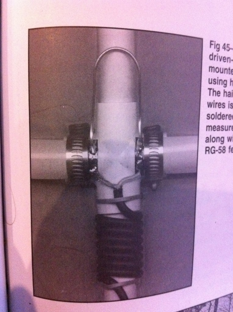
Take your coax and make 8 turns around the PVC. Secure with electrical tape. The author claims a 1.1:1 match at 146.565MHz. Tuning is done via spacing between the two halves of the driven element. If you used super glue, you can break the bond by bending the measuring tape back from the PVC and re-gluing. The hose clamps work best for adjustability, obviously.
That’s it! I opted to keep the extra few feet of PVC on the bottom, so that way I can hold it under my arm and keep both hands free to adjust my radio, write things down, or whatever. You could cut it off shorter to use as a “hand held” beam. Here’s what mine looks like. It’s great, because you can take it with you in the car; just toss it in and don’t worry if the elements bend–they’ll snap right back!
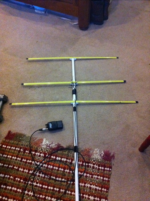
Here’s what mine looks like after adjusting and soldering the matching section.
